Mobirise
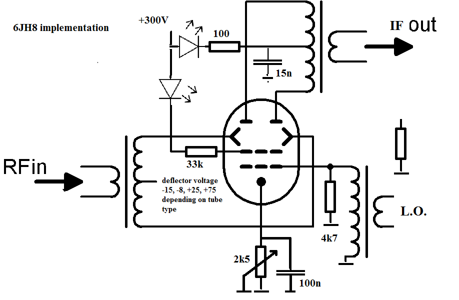
Beam Deflection Tube Mixer


Beam Deflection Tube mixer for my navtex receiver

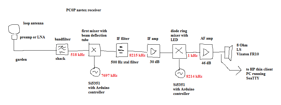
My navtex receiver is connected to a loop antenna from Wellbrook. It has an LNA mounted at the foot of the loop and a coax cable with RF and 12V. 
Indoor is a small box, where the 12V is separated from RF. The LNA has a decent gain, so i can mix this 518 kHz navtex signal directly to IF.
I wanted to have a mixer with good high level performance, as the navtex frequencies are close to the medium wave broadcasting band. I need to add that the last few years (2016 - 2018) a lot of AM transmitters have been switched off, reducing the issue. 
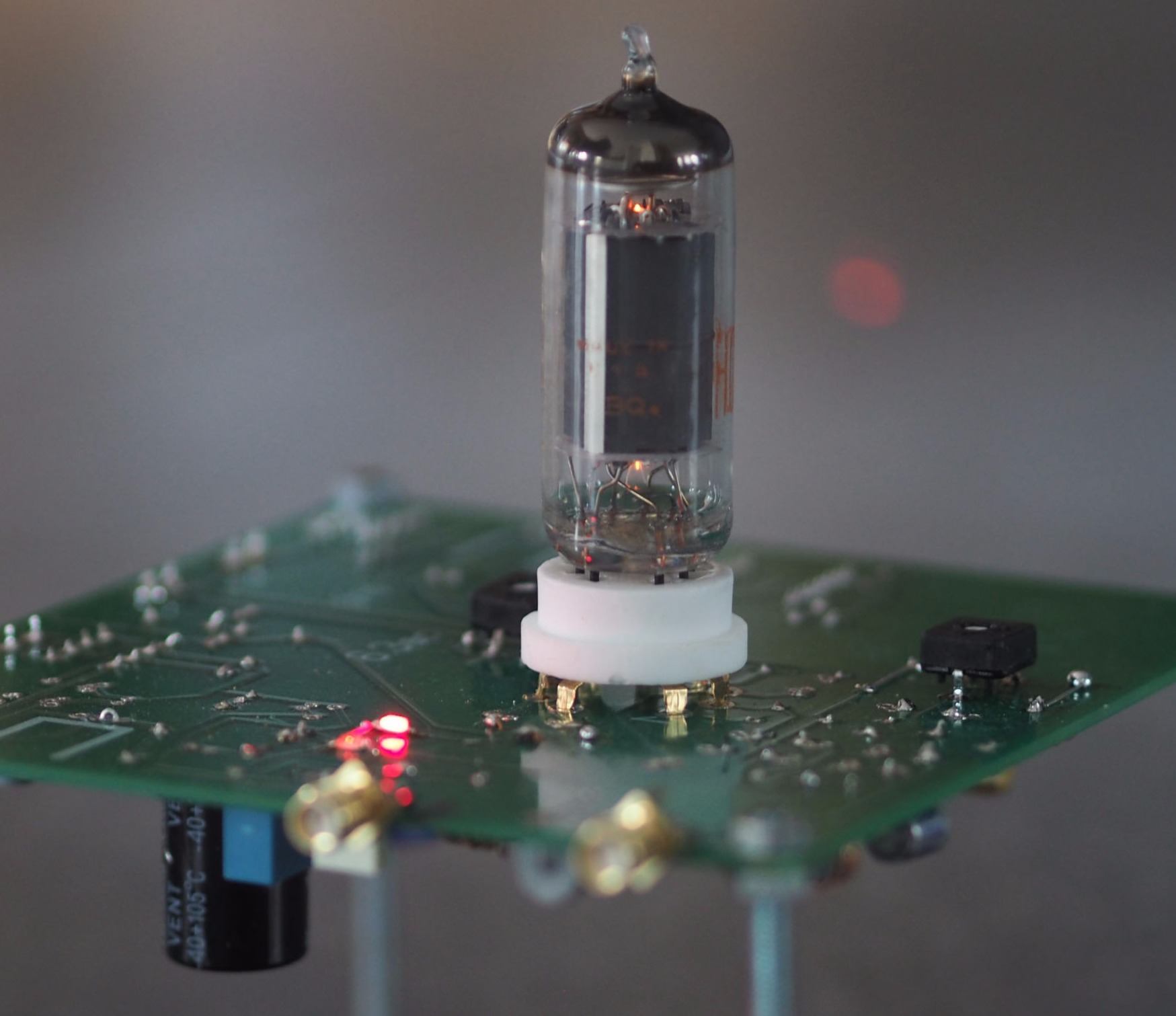
I also wanted to use a tube or valve for nostalgic reasons and because i also use them  in my audio hifi system.
Therefore i started to search for tube types that could do this job, and i bounced on the beam deflection tube. They are only produced for the american market so far i can see, to demodulate the NTSC color signal in TV receivers. 

Mobirise
Create awesome websites!

As a reference, i draw the receiver schematics above. The signal from the loop antenna in the back of my garden arrives in my shack via a long RG58 coax cable. It end in the aluminium box supplied by Wellbrook where the 12V enters the cable and where the signal from the preamp comes out.
I have made a bandfilter of 370 - 520 kHz to be sure that no strong signals from the Medium Wave band get into the mixer.
The most popular beam deflection tube is the 7360 tube from RCA, used as a balanced modulator or balanced mixer. This tube is getting rare and expensive, and there are several good or even better alternatives. The beam deflection tubes for american colour TV sets can well be used as a balanced mixer, stating the 6AR8, 6JH8 and 6ME8. I have tried both the 6AR8 and 6JH8 with good results, but the 6ME8 can be used also with the same results.
Data sheets from these beam deflection tubes or valves are available on the internet. It is worth to have a look at them to check the simularities and differences.  Please find below the typical schematics of the deflection tube as a first mixer:
  

Mobirise
Create awesome websites!

The picture above comes from wikipedia, with a few changes done by me. I will discuss the tube simularities and differences below.
All tubes use 6.3V for the filament, and about the same current of 0.3A, that's easy. I simply used 6.3V ac for the filament, as it is simple and the 50 Hz is no issue. Be careful with the filament pins:  pin 4 and 5 are the standard heater pins, but watch out (!!) : pin5 must be grounded, pin4 will get the 6.3V. It is stated in each datasheet, but easily overlooked, and guess: i did it wrong the first time.
As you can see, the bias Voltage for the deflectors is the main difference between the tubes. 6AR8 and 6JH8 need a negative Voltage and 6ME8 (and the 7360) need a positive Voltage.
The positive Voltage is simple, one takes a resistive devider, use the Anode Voltage of 250V, and devide it down to +25 or +75V.
For a negative Voltage, i used the 6.3V AC and used a rectifier/doubler to make a negative Voltage of say -18V. Then a resistive devider and done. It looks like this: 


Mobirise
Create awesome websites!

The capacitor should be an Elco of 100uF / 25V and the diodes: you can use nearly any. I used the 1N4001. So this negative rectifier - doubler you can use for the 6JH8 or 6AR8. 

Mobirise
Create awesome websites!

About the cathode circuit. The first grid is grounded, so the cathode resistor will determine the anode current. I made it with a trimmer, as the RF response heavily depends on it. I added two LEDs, one for the anode current, one for the accelarator. When setting the trimmer to nearly zero, the Anode LED will be bright, with a total anode current of say 15mA.  With 300V there will be 4.5W of total anode dissipation, that's near or over the top. Also the accelarator LED will be pretty bright. Listening to the output of the mixer, you will have a lot of output and relatively poor suppression of the local oscillator. Increase the trimmer in such a way that the anode LED is half bright, the accelarator LED is a little bit on, and you are there. In my mixer we are talking of 5-7 mA total anode current and a small 1 mA for the accelarator.  A bit more about local oscillator suppression when the deflector circuit is disdussed. The total transfer of the mixer may be from about +4dB for a relatively high current, so maybe -4 dB for a medium current. 
The anode Voltage is 300V in my circuit with the 6JH8, as this tube cab handle it. With the 6AR8, i used 250V, reduced the 300V a bit with a series resistor. The anode voltage does not need to be stabilised, a simple rectifier and a CRC network will do. 


Next part is the local oscillator injection. Local oscillator is injected on the first grid of the tube. The level is such that it switches on and off the complete anode current. Looking in the tubes datasheets, to switch an Anode current from sax about 10mA to 0, it needs about 6V Ugs. In my case i am using the Si5351 , providing 8mA max in a certain output impedance. I have used a  transformer to bring the output voltage and terminate it in a relatively resistor of 4700 Ohm. The transformer is a 1:4 transformer, and the impedance is doing 1:16, the n to the power 2.  The impedance seen by the Si5351 is 4700 / 16 = 293 Ohm. With a current of 8 mA max, this is about 2,3V. The output Voltage of the Si5351 is limited by the power supply Voltage, so 3.3V. Total swing on the grid will be about 3V x 4 = 12V. I have measured about 10Vtt, this is enough Voltage to switch on and off the tube correctly. The Si5351 produces a square wave, so the output will have several harmonics. It may be possible that by setting the cathode resistor with the trimmer, more or less harmonics switch on and of the tube. My impression is using a small cathode resistor value, there is more noise adressed by the higher harmonics of the square wave.

Finally some results! I injected -20 dBm on 518 kHz into the mixer. Output was -20 dBm also at the IF frequency of 8215 kHz. This means a transfer of 0 dB, not bad at all!. Anode current is about 12 mA and Anode Voltage is a small 300V. The local oscillator level is about + 10 dBm at the grid, and i could balance the output so that at the l.o. level was not more than -35 dBm out. So about 45 dB l.o. suppression. I increased the input power to see what output power i could achieve: about + 10 dBm. I guess that the l.o. level was limiting this, but + 10dBm as -1dB level is not too bad. Next step are intermodulation measurements, that needs a little preparation.


Made with ‌

No Code Website Builder