© Copyright 2019 Mobirise - All Rights Reserved

(for SAQ, go to menu at top right)

Buffer Stage for Audio DAC
where the valve meets silicon

Development of a tube based buffer, to become a Raspberry Pi HAT. Does is fit? How does it sound?


It all started at the end of 2019. I have been working at my Navtex receiver for most of the year, I was happy with it. Time to do something in the audio domain. Looking back, in 2010 I started to build my first tube preamplifier, after getting inspired by mr. Lampizator. I bought a Wolfson demo board, and connected a SRPP to it. Trying to understand the DAC interfaces like I2S, I got it up and running. In 2013 I designed the first Maud Dac, a Wolfson WM8740 connected to a 6N30P. A CM6631a to convert USB to I2S. 
When the first Raspberry Pi came out, I bought a HifiBerry DAC and started to play with it. I made my first Raspberry Pi HAT Dac, based on the AD1859. This DAC was and still is a nice alternative to the widely used PCM52xx series. I researched many different preamplifier topologies and ended up reading a lot about Ale Moglia's work. At that time he was optimising the Hybrid Mu amplifier, and I could actually support him a bit by selecting some mosfet's for the Gyrator in this stage. 
Then I realised how nice it is to use both parts from yesterday together with state of the art silicon semiconductors. To use both the tube or valve where it makes sense (literally) and use silicon where they glance. 
In the mean time the Allo company came on the market with the Kali, a reclocker HAT for Raspberry Pi, named after the Indian Goddess of time. It first of all gives a much sharper image of the sound stage, and it also provides a Master Clock (MCK). With the MCK available, one can use all available DAC's, as most DAC's need this Master Clock. It is now possible to use the DAC's from AKM, Wolfson, all the higher end DAC's actually.
I designed the HAT DAC for Raspberry Pi 3, based on the AD1852. I have a few in action, enjoying them a lot. I find it a bit hard to sell, as I did with the AD1859, as the customer also requires the Kali. I don't work for Allo, but I do believe that every serious RPi-er with audio grooves should get one.
It is becoming quite a long intro....one of the wishes i had was to see if it would be possible to integrate a preamp or buffer to the RPi HAT DAC, and if possible one where the glass meets the silicon.   As you can guess: the answer is yes! I'll describe the process and the result in the next lines.

Mobirise
Create awesome websites!

The idea for this type of source follower comes from the valve radio website in Australia.
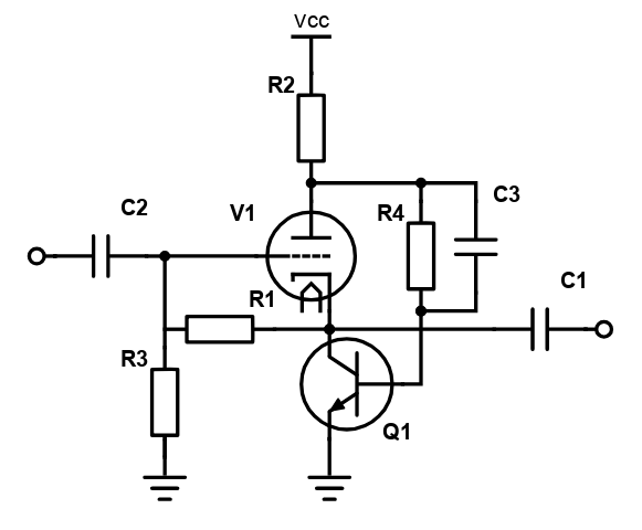
www.valveradio.net  / radio / lowdistortioncathodefollower  . The normally used cathode resistor has been replaced by a transistor. This transistor samples the anode of the valve, amplifies this and provides local negative feedback. This webpage gives a nice qualitative analysis of 2nd order distortion, and the suggestion to apply this local feedback. I will not repeat it, please have a read at this very informative website.
I will focus on the requirements to use this building block as an RPi HAT. I have the following requirements:
1. Low Voltage. RPi HATs are open, and will be touched. I want to use 50V as maximum, and 48V as a target voltage, as power adapters are available for this voltage.
2. The valve involved should be well available and not be too expensive. It should show adequate performance at this low voltage.
3.Use a Voltage Out DAC without build in opamps to provide a clear path to this Buffer.
4. If possible, the Buffer should be able to provide enough current to support some head phones.
As I already designed a DAC for RPi with the AD1852, it seems a logical step to use it.
5. Gain is not required, as most final amps have more than enough gain. Low output impedance is nice as it supports the double bass.


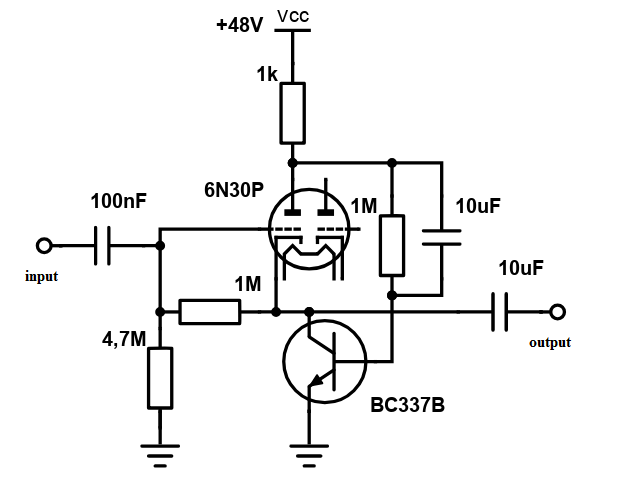
As I already designed a DAC for RPi with the AD1852, it seems a logical step to use it. The first valve i tested is one of the steepest double triodes available: the 6N30P. It has about a gm of 15mA/V, a mu of 15, so an ra of a 1kohm. It fits the low voltage requirement.

Mobirise
Create awesome websites!

I'll discuss some settings: Vanode = 35V, do Ia = 48-35 /1k = 13mA. Hfe of BC337B = 270x, Ic= 13mA, so Ib = 48uA. Ib should be 35-0.65 / 1M = about 35 uA. This is a hfe = 371x. The transistor is mounted close to the valve, heating up the transistor. Hfe increases with rising temperature. With this Ia and Uak, Ugk is about -1 V. I lifted Uk a few Volts to give the transistor Uce some headroom. The Ugk develops a small current through the 1Mohm resistor( 1 uA). This current flows through the grid to ground resistor, pushing Ug and Uk up.  Ug is about 5 V and Uk 6V. Uin = 1Veff = 1.4Vt = 2.8Vtt. Output voltage Uk = Uc of the collector. The collector voltage swings about 1.5V up and down. With a Uc of 6V, this is well possible. The relatively small Ugk is ok, as the signal voltage on the grid and on the cathode are in phase, and grid current is about 0. Feedback capacitor is shortcutting the feedback resistor of 1Mohm. This gives the required negative local feedback for audio. ri of the transistor is hfe x re. re = 25mV/Ie. re = 2.5Ohm at 10mA, hfe = 270, so ri = 675 ohm. Cfeedback should have an Xc of max 675 Ohm at 20Hz, so C = 10uF. 
To get maximum loopgain, the Ra of 1kOhm should be a few times more than ri of the transistor. Otherwise some some signal is lost in Ra. Simply increasing Ra means simply increasing the supply Voltage, that's not wanted. We need to increase Ra for audio using a gyrator.


Before going to the gyrator, i'll discuss point 4 of our shopping list, current for the head phone, or output impedance. Output impedance of a cathode follower is the parallel resistance of 1/gm of the valve and the Resistor Rk. Usually 1/gm is the dominant factor, with the 6N30P and a gm of 15mA/V, rout is 66 Ohm. This is already a nice small figure, but the negative feedback reduces rout even more. rout is reduced by the loopgain, and is basically equal to hfe of the transistor. This means when hfe is something like 200-300x, rout is below 1 Ohm. (!). I have tried to measure it, and the rout was determined by the output capacitor impedance, not the active circuit. It is clear that when to enjoy this low output impedance, this capacitor should be large. When the buffer is followed by a potentiometer and final amp, the potmeter resistance loads the coupling capacitor. RC time determines the low frequency (bass) behaviour. When R = 10kohm, C could be 2.2uF or a bit more. But when you connect a head phone with R = 50 Ohm, C should be 100 times more. At the moment i use an Elco of 100uF, and it sounds well. I have a 100nF MKP Vishay in parallel to support the high frequencies. When using the 6N30P at 15mA, one can use head phones using 7mA and 0.6V , so a small 100 Ohm or more. These are relatively high impedance head phones. 


Gyrator. I want to change the anode resistor of 1k Ohm for a gyrator. I see the following reasons:
Reduce Voltage drop over anode "impedance" and therefore creating more anode-cathode voltage.
Making sure the anode impedance is dominated by the ri of the valve, ri of transistor, not anode resistor.

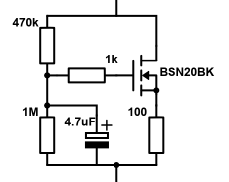
The gyrator is use looks as follows:

Mobirise
Create awesome websites!

The gyrator is basically a source follower, where the signal is "planted" at the gate via the capacitor and used at the source. Planted at the gate means that the input circuit has a high impedance, not loading the source of the signal, in our case the anode of our valve. The source of the mosfet is following the input (gate), so looking at this 100 Ohm source resistor, both sides of the resistor have the same signal voltage. If both sides of the resistor have the same voltage, there will be no signal current flowing through this resistor. In other words: for audio signals, this resistance is very high! In high contrast to the dc current, the anode current, and this current is not small at all. In our case somewhere 10-25mA. 
How much voltage stands over the gyrator?
If we assume 20mA of anode current (quite  a lot), U over Rs = 100x20mA = 2V. The mosfet has a Ugs of about +1.5V for these currents. The gate stopper R of 1k supports no current, so no V. Over the 1M bias resistor we see 2+1.5 = 3.5V. This means 3.5uA, flowing also through the 470k bias resistor, doing 1.75V. So total voltage = 3.5+1.75V = 5.25V. Means Uds = 5.25-2= 3.25V. Good value, looking in the datasheet. 
This means that the comparing the original situation of 1k anode resistance and 20mA would lead to 20V voltage, and now we a bit more than 5V voltage. This nearly saves 15V we can use as Uak and have a useful valve set point.


In the last 2 weeks i have been using the Valve & AD1852 HAT while on business trip. As a valve i have used the 6B4a valve and the gyrator as described above. I used it on my AKM head phone with 55 Ohm speakers. I simply sounded precise (Kali, transistor local feedback), layed back (valve, output caps) and powerful(current, low output impedance).
I am not happy yet with the fact that the 6B4a is a single triode, so the need of 2 valves on the small board. It also needs 2 times power for the filament, that is maybe avoidable with a double triode.
Therefore while enjoying jazz music from ABC Jazz (again from Australia), i was searching for high gm double triodes. I may have found one, the ECC2000 and i bought a few pieces to test out. Looking at the data sheet, they may do a 20mA at 50V Uac, are widely available and only use 0.4A filament current at 6.3V, say 2.5W of glowing power. With a bit of luck i can do a test with them in the next weeks and check the sound and lineairity of them.


Loopbandwidth and Stability
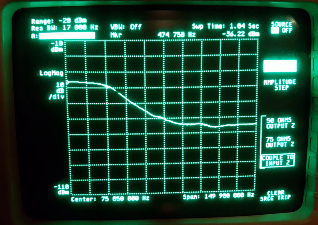
One more issue i want to address in this paragraph. The extra gain of the local feedback transistor gives a lot of extra loopbandwidth. One must assure that the circuit remains stable when adding this loop gain. I did not encounter any oscillation or so, but it's good to check. Luckily i have been able to buy a spectrum analyser last year for a reasonable amount of money. It has a  built in sweep generator, so i could sweep the buffer and check it's transfer. First of all, the total bandwidth of this buffer is about 35 MHz (!), it could easily work as a short wave amplifier buffer. But at the end of the bandwidth i saw the transfer peaking up, indicating some instability. The cure is already mentioned on the valve radio.net website. Thanks for this, Alex. Using a small capacitor (some pF) between the transistor collector and base will do the job. It reduces locally the transistor' bandwith, creating a flat transfer of the buffer as a whole. I tried out a few small capacitor values while looking on the spectrum analyser. A value of 22pF i used, giving a flat transfer up to the same 35 MHz. Adding this small capacitor is a simple solution to assure global stability. I will make a few spectrum analyser pictures and add these to this page.

Made with ‌

No Code Website Builder