Mobirise
SAQ or how to receive...                        very low frequencies


I just received the invitation for the December 2024 transmission:
Sunday December 1st 2024.
At this day, it is 100 years ago that the operation started and the messages could be received at the other side of the Atlantic ocean. 


For questions and remarks: paul(at)prinz.nl  (test with offline webpage builder)
When my collegue Andre mentioned the frequency, I thought: wow , this is an audio
frequency: 17.2 kHz! What antenna to use, and what sort of receiver? How not to receive all the switching power supplies that we have in use? On this web page I will write my findings and you might be inspired to also try to receive the very long wavelengths.  

Mobirise

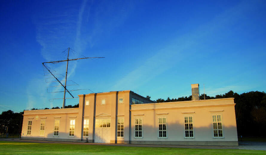
Grimeton or Varberg Station, call sign SAQ

The radio station was built between 1922-1924 and used for transatlantic communication. This was done at a time that short wave comms via ionospheric layers was not yet fully understood. In the 1950s the station was used to transmit to submarines. This was done up for another 40 years. The radio station is now on the Unesco World Heritage List. You can find more information via the website links below:
Unesco         or     Alexander association    .
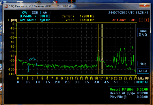


Today is the day after. Yesterday it was the 24th of October 2020, the UN celebrated it's 75th birthday. I worked for the UN from 2004 to 2007 and I feel it still is a bit my organisation. Yesterday it was the first day that we, the partners in crime team, could test the preamplifier with tuned ferrite rod. Please have a look at the pictures and the sound files.


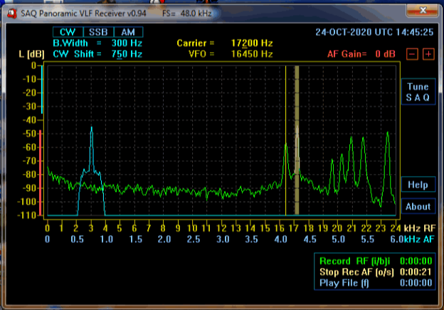
I made these spectrum pictures in my car, at a location just outside my village. The preamp with tuned ferrite rod was pointing east-west, so reception was north-south. I tuned the rod using 1kHz bandwidth as you can hear the audio pitch changing. After that I used 300Hz CW bandwith for receiving the message. Noise level can be seen at the left, around -75dB. Key down is at the right, a level of -45dB. This means a S/N of 30dB, an amazing level! Below I will add some more pictures and the sound files recorded with the SAQ panoramic receiver software. 
Wilhelm was also on the road parking at a quiet spot. He also received SAQ with very comparable figures. 

Please have a listen to this audio file. I recorded it on the 24th of October 2020 inside my car. It was the message transmitted for the celebration of the UN 75th birthday.

The Receiver: I checked several web sites to see what other people are doing and I saw 3 solutions:

First solution: Superheteodyne receiver.
See the website vlf.it . Look for: A very simple VLF Pocket receiver by By Wilfried Fritz, DJ1WF. It is a classical super heteodyne receiver with an IF of about 455 kHz and a BFO. Using a short whip receiving the E-field.

 Second solution: PC, Laptop, Sound card.
This solution comes from the Alexander association, the guys that run and maintain the old Grimeton Station. The transmitted frequencies are that low that they can directly be received using  a laptop soundcard. The PC then uses a simple SDR program to process the incoming frequency.  More information can be found using this link:

Receive SAQ

It suggest to use a PC or laptop, take the build in sound card, and receive it directly. As most sound cards sample on 44.1 kHz or 48 kHz, the spectrum up to half of the sampling frequency, so 22 or 24 kHz can be received. 

Third Solution: Upconverter.
The third option is to upconvert this low frequency and convert it to a frequency that most short wave receivers can handle. 


I chose to explore the second solution: use a laptop with sound card. When you have a look on the Alexander Associations web site, you will see that SM6LKM, Johan Bodin, wrote a nice SDR program. It receives a carrier in the vlf band up to about 24 kHz and demodulates it. The program easily installed on my laptop and this part of the game was done. 
The software can be found here:
https://sites.google.com/site/swljo30tb/home/files
.


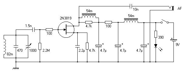
I have found a contribution on a radio communication board: www.theradioboard.com. It's a 2013 contribution from Broesel out of Villach, Austria. Thanks Broesel. He published a front-end using a ferrite rod and capacitor tuned with parallel resonance to about 15-20 kHz. The front-end uses a jfet as preamp in grounded source configuration and the output is fed to a soundcard of a laptop. His contribution is found below.

Mobirise
Create awesome websites!

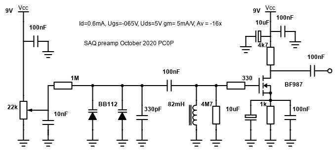
I changed his contrbution a bit to allow easy reproduction. I am using a varicap (varactor, capacitance diode) with a potentiometer to tune the preamp. I used a simple load resistor and not a complex combination of LCLC as it is too difficult to make. A simple R as load reduces the gain compared to the LCLC solution, but still provides enough gain in the stage to get a good pre-amp.
I used a japanese mosfet at first as was available, but other fet's will work fine too.

Mobirise
Create awesome websites!
Mobirise

VLF receiver SDR on laptop from SM6LKM

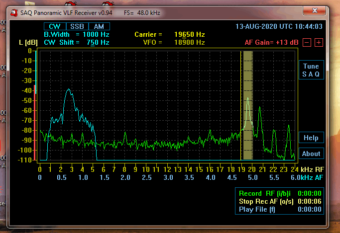
The green spectrum shows the vlf frequencies coming into the sound card. The blue spectrum at the left is the demodulated audio. Here I tuned in to a submarine transmitter in the UK on 19.65 kHz. 

Ferrite Rod with Copper Coil

This is maybe the most important part of the receiver! And the nice thing of it is : you only need this! No very long wire antennas, grounding rods, huge magnetic loops. Just this rod, go a bit outside your house to avoid picking up switching power supplies. Have your laptop one meter away or so from the ferrite rod. Start the SAQ SDR programme from SM6LKM. You can listen if the frequency is clear, otherwise go to the clear. 
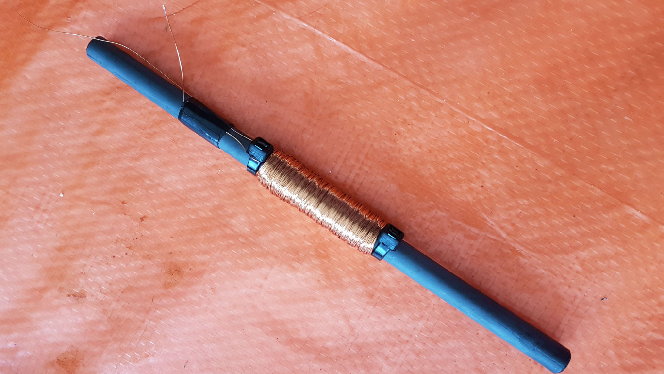
The ferrite rod is a classical magnetic antenna used in medium wave or long wave receivers. Get the longest and most thick one you can find. I used two tiewraps to lock the coil and started winding. The wire is lacquered or enamelled copper wire of 0.25 or 0.3 mm (28 to 30 AWG). We need a lot of windings: around 900 (!) to get to a inductance of 82mH. A bit more or less is not important.
Mobirise

After everything was working, I tried to reverse engineer the Coil. I found out the following things:
Over here in Europe, most ferrite rods are made of only a few ferrite materials,

all from Ferroxcube Philips: 4B1 and 3B1.
Well, I did some more searching and the list is a bit larger:
4B2, 3C90, 3S3 and 3F3 ferrite material.
The permeability mu is the important parameter, the higher the mu, the less windings to make for the same induction L. I will sum up the mu value for the different ferrites:
4B1: 250,     4B2: 250,     3B1: 900,    3C90: 2300,     3S3: 350,     3F3: 2000


So we see quite a difference in mu and we want to go for a rod of 3C90 or 3F3 material, otherwise we wil go for a 3B1 rod, that's also fine.

You can also look at it from a material perspective. What material the rod is made from? I believe this gives a good indication:
NiZn so Nickel Zinc. mu value of a few hundred, used for some MHz
MnZn so Mangan Zinc, mu value of around one thousand or so, used for some kHz
The datasheets will tell what materials are used. 
So if no mu is given, get a MnZn rod. I will verify this by testing.
This website Ferroxcube gives good info on material and mu.


I went to the website: COIL to calculate the inductance L for a mu of 250 (4B1) or 900 (3B1).

This Coil online calculator helps in managing expectations.
To understand the influence of mu, I did the following exercise:
Take a "standard" rod of 18cm length and a diameter of 10mm and vary mu and see how many windings we need to get to get an L of 82mH:
mu = 250 --> n = 1036
mu = 350 --> n = 933
mu = 600 --> n = 840
mu = 2000 --> n = 759
This exercise shows that when you change mu by a factor of 10, from about 200 to 2000, the number of turns required changes only 25%, from about 750 to 1000. This means 2 things:

1. If you don't know the mu: use 900 turns and see  the result
2. getting a high mu rod is nice but not that important


It is January 2023 and I am updating this part:

Where to buy ferrite rods or bars:
 

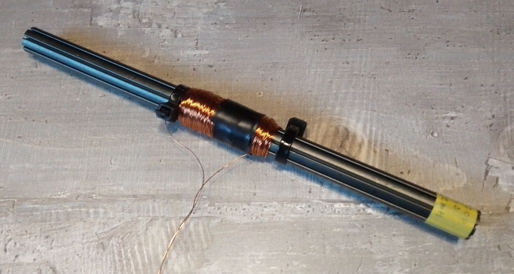
A. Contrans Ti in Poland. www.contrans.pl  .They are manufacturing magnetic material and run a web shop. Go to ferroxcube, soft ferrites and impeder cores. I bought the 20cm, 12mm diameter rods from 3C85 material. This has a mu of 2000 and is first of all well documented. The grooves in the bar are no big deal, I have not noticed some influence on L or so. I made a coil of about 5cm, so 25% of the rod length. I needed 810 turns to get 82 mH. I have noticed that it makes sense to stay away from the rod ends as at the end you 'see' air with a mu of 1.... Do not make long coils with maybe 2 layers, it is more effective to make shorter coils with 5 layers. 


B.   I looked at the webshop box73.de.   I went to the page with the ferrite rods:
Ferrite Rod at box73.de
Here you can buy a rod of 3B1 material and diameter of 8mm.
B. The second source is ebay.de and the webshop: 
electronic-componentsseller
He sells various ferrite material, when you seach for "FERRIT" AND "3F3" you will find a great ferrite rod of 3F3 material with a length of 100mm. 

C. Electrodump in the Netherlands:
https://elektrodump.nl/en/Ferritte/2112-ferrite-rod-10x160mm.html
These one I used, mu about 350, n = 900

D. Irish Electronics:
https://irishelectronics.ie/epages/950018241.sf/en_IE/?ObjectID=12719137
 This rod is a bit short, 10cm, but it is available.

I will show another coil creation that all have the required inductance of 82mH.
It is a grooved rod , impeder core from Contrans Ti in Poland. This one has a length of 20cm, diameter is 12mm, 3C85 material with a mu of 2000, 810 turns.

Mobirise

I am updating this part of the webpage and/but stick to my previous conclusion:

buy the longest and fattest rod you can get, do 900 turns

and be happy! Maybe easier than looking for the holy grail.
The Coil I connected to the preamplifier. The preamplifier is using a 9V battery to keeps things portable. Its rechargable, the preamp uses small power, you can listen the whole day outside and recharge it over night. Pointing the ferrite rod towards Sweden will give you minimum reception, it's a sharp null, the rod needs to be perpendicular to SAQ. That's not critical, and you can use this maximising and minimising to cancel out a disturbing carrier on a nearby frequency.  

Mobirise
Mobirise

What to receive?

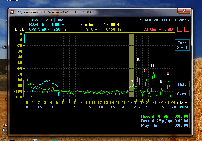
The spectrum picture I took just outside our village. It shows a couple of things:
1. there are no interfering disturbances
2. noise level is -100..-105 dB, just above the sound card level. 
3. Preamp is tuned to SAQ on 17.2 kHz. The demodulated bandwidth is clear. Waiting for SAQ to transmit at Christmas time....
4. Input noise (green) at 17.2kHz is about 10dB more than preamp noise. That's fine.
5. The carriers A, B, C, D and E are:
A: SAQ at 17.2 kHz, Sweden
B. HWU at 18.3 kHz, France
C. GBZ at 19.65 kHz, UK
D. HWU at 20.8 kHz, France
E. GBZ at 22.1 kHz, UK
F. DHO38 at 23.4 kHz, Germany


About the schematics:  
 The gain of this preamp is the gain of a common source configuration. This is basically : Av = -gm x Ro.  Ro is the parallel set of 3 'resistors', ro of the fet itself, Rd (2k7-4k7) and Ri of the sound card (assumed 10k). ro of the fet is much higher than the other two, so can be neglected. Ri is something that can not be influenced, and Rd can be chosen. I chose Rd a few times smaller than Ri, so that the gain is determined mostly by the preamp and not by the sound card. I chose Rd high enough not so have a lot of Id as it would draw the 9V battery empty. I chose a fet with relatively high gm at lower currents, and a small capacitance Crss between gate and drain. This is important as we have a resonant circuit at the input, and Crss gives feedback from the output back to the input. At the beginning I used a fet with a Crss of 6pF and it made the preamp oscillate. A Crss smaller than 1 pF is recommended. Ci smaller than 30pF is also fine, this is not so critical.
A small resistor is series with the gate (gatestopper) is used to avoid oscillation at VHF frequencies.
The 4M7 resistor grounds the gate, so that the fet is set also when the coil is disconnected.
The resonant circuit is made of the ferrite rod inductance together with 2 capacitance diodes and a fixed capacitor.  The 2 capacitance diodes have a total capacitance of about 1000pF or 1nF. The fixed capacitor is chosen such that resonance occurs a bit below the SAQ frequency of 17 kHz. I selected 330pF, so a total Cp = 1330pF. With an L of 82mH, fres minimum = 15 kHz. The actual fres min was a bit lower, so I guess that the capacitance diodes have a capacitance a bit higher than 500pF each at 0V. At 8 or 9V, the capacitance diodes only have a capacitance of 34pF max each, so Cp (8V) total is 68pF + 330pF = 400pF. Therefore fres max = 27 kHz. This gives us a frequency range of 15-27 kHz and that is fine. If you want a higher fres max, remove the fixed capacitor and use 3 capacitance diodes in parallel.
The diodes draw a little current, I measured 1V drop over the 1Mohm resistor, so both capacitance diodes draw 1 uA in total. No big deal.


Shopping List
FET                        2SK241-GR, tested and preferred, 2SK161-GR Rd = 2k7 and Rs = 330 Ohm or

FET                        2SK161-Y, tested. Rd = 4k7 and Rs = 470 Ohm. Works fine.

FET                        2SK193-p or k. Rd = 2k2 and Rs = 47 Ohm or

FET                        2SK522-d. Rd = 2k2 Ohm and Rs = 220 Ohm or

FET                        2N3819, Rd=2k7, measure Ud and change Rs so that Ud = 4.5V +/-1V or

FET                        BF410b. Rd=2k7, measure Ud and change Rs so that Ud = 4.5V +/-1V or
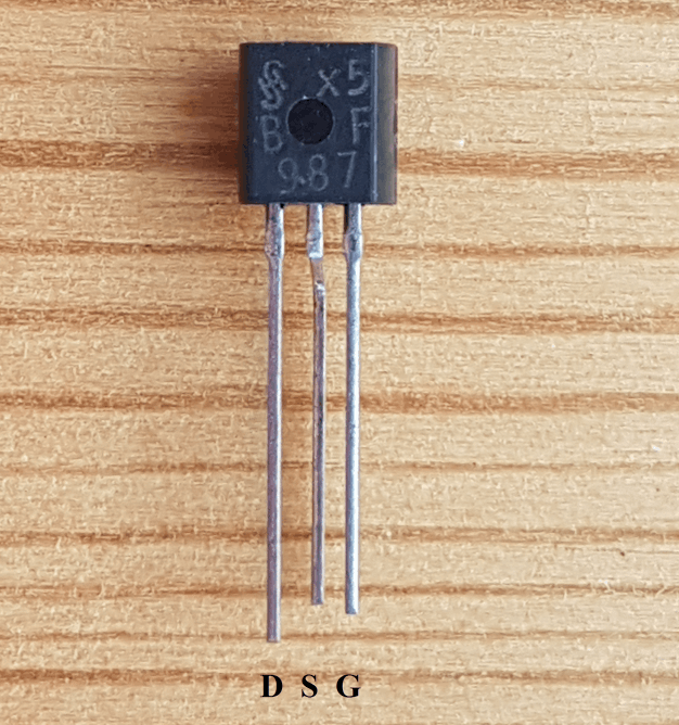
FET                        BF987. Tested.preferred.Rd=4k7,Id = 0.5mA,Rs = 1kOhm. Pinning below near picture
FET                        2N5485 or 86. Rd=2k7, measure Ud and change Rs so that Ud = 4.5V +/-1V
FET                        BFW10 or 11 or 2N4416. Rd=2k7, measure Ud and change Rs so that Ud = 4.5V +/-1V

Ferrite Rod          round, diameter 8-10mm, length 100-200mm, if you can choose: high mu

Wire                       lacquered or enamelled copper wire, 0.25 - 0.3 mm, 30m length

Varicap                BB112 (EU) or 1SV149(Japan)  2x or one KV1270, KV1560 or BB212 (2 diodes in one)

9V                        Use 9V monoblock. Simple. Rechargable or not. 

LED                      Use a bright LED with bias resistor. R=10-22kOhm. So you don't forget to switch off

Potmeter            22k. Any lineair potentiometer will do. Value from 10k to 100kOhm. 
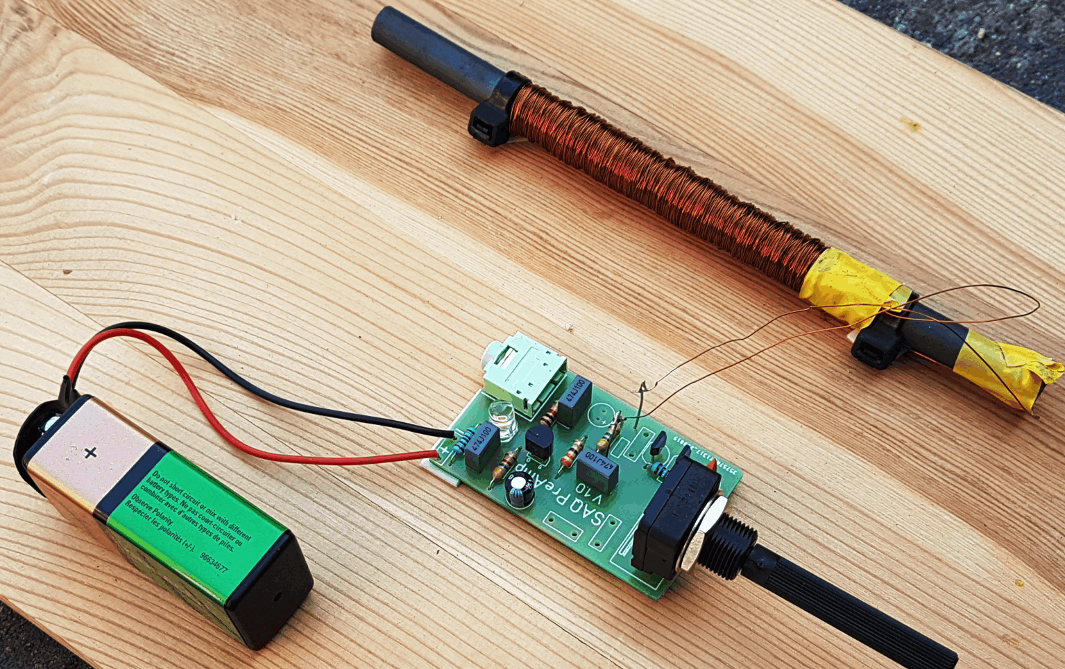

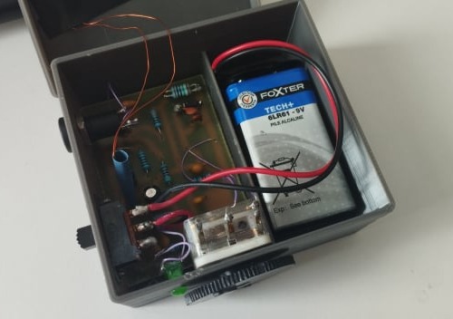
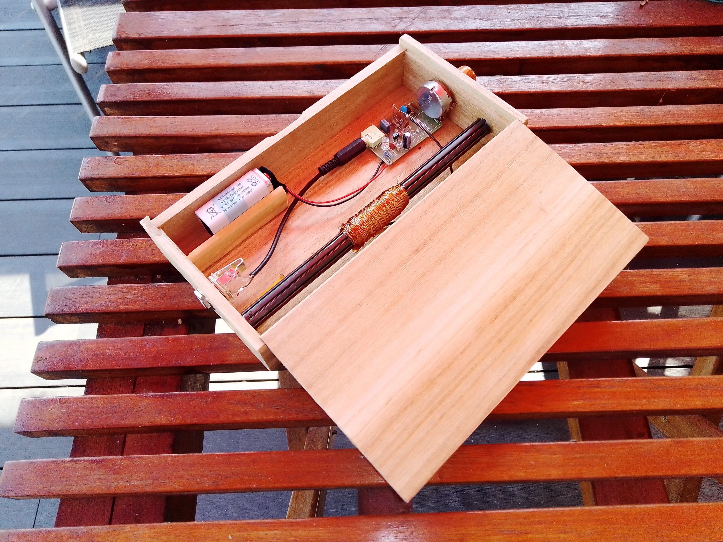
The picture above left shows a small PCB that I have created. For people that are interested, send an email to paul(at)prinz.nl  . The rod I used here is the 3B1 rod I bought from box73.de  . With the potentiometer I tune from around 13 kHz up to 26 kHz. This set up I am putting in a small wooden box to be prepared for the SAQ Christmas transmission. The results look promising.

At the right you see how to connect the BF987 fet as the datasheet is not very clear. I bought some more of them, if you want I can provide the fet to you.
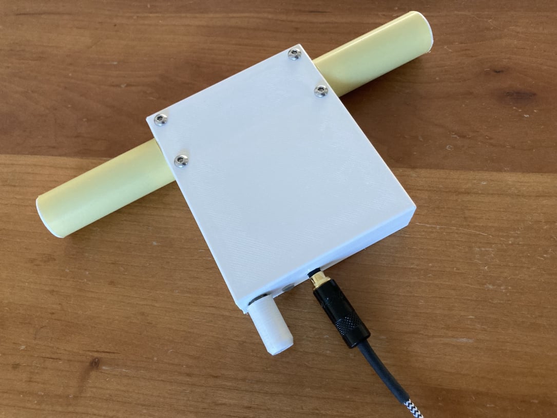
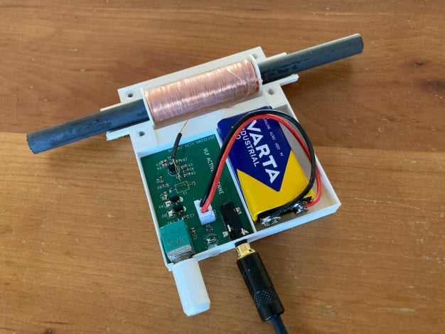
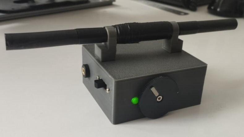
On this page, I am going forth and back in time. I am now and then getting some response on this page. We are talking June 2024 and SAQ Grimeton is doing the preparations for the 100 Year celebration! I got a message from Rens, PA3AXA. He did together with some other radio amateurs an amazing job. They created a PCB and designed a box for the PCB and ferrite rod. Pictures do say more than a thousand words:
Pictures below and amazing results by courtesy of Rens PA3AXA


For your information: Rens used the ferrite rod from:
https://elektrodump.nl/en/Ferritte/2112-ferrite-rod-10x160mm.htm
The FET is a 2SK241gr. The FET, the varicap diodes and the potentiometer he bought at Aliexpress. Wire diameter is 0.2 mm and number of turns is 900, the inductance is about 80mH. 
Rens made the PCB files and the 3D printed box + ferrite holder available.
Please find the links below, there are 2 zip files, one for the PCB, one for 3D printing.
3D printer files         PCB files


SAQ Panoramic VLF Receiver v0.94
OK. My colleagues and brothers in arms are also preparing themselves to receive the October 24 2020 transmission.
And of course some issues are popping up to be discussed over here.
The SDR Panoramic receiver from SM6LKM has it's little issues, easily to overcome. SM6LKM states that the software is designed for Windows XP. But....I have two laptops over here, one on Windows 7 and one on Windows 10. Both of them run this SDR software. When you run the software, i.e. SAQ48k, the following error occurs:


This happens on both Windows 7 and Windows 10.
This error is related to the program not seing any audio input. When you do not have any microphone or line input activated, this error occurs. Your audio recording devices look like this:

Here you can see that the bottom input is disabled and the middle input shows that the cable is not plugged in. When I plug in the cable from the preamp, it looks like this:

Even when you do plug in an audio cable, this action is sometimes not recognised. This means that our famous microsoft product did hang itself up.  Restarting the laptop always solves this issue and then you will get the picture above. Only when you have the picture above it is useful to start SAQrx and then it will always start up properly.
So make sure your audio input is activated and then start SAQrx

For Windows 10 it looks like this:
 

Sorry for the German language, but I guess that you will understand:


The next topic is the CW bandwidth. When the program starts up, the CW bandwidth is set to 1 kHz.


Like here on this picture. 


By accident I clicked on the CW button again and voila: the bandwidth changed! Please try this out for yourself. I like the 300Hz setting as it fits nicely to the RTTY PSK and FSK transmissions to the submarines. I will check out what filts well to the SAQ cw transmission. Yes, I can confirm that 300Hz suits the SAQ cw transmission well.
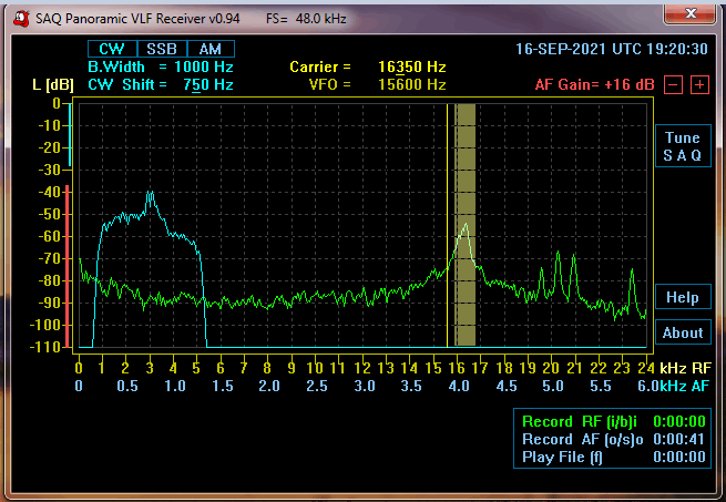


This is an update of July 2021. There has been an SAQ transmission on Alexander day, unfortunately I couldn't listen as I was travelling. But a few weeks later, I got an email from PE7B, Paul Webster, informing me that he also build this ferrite rod preamplifier. If you want to, have a look at this youtube channel :
https://www.youtube.com/watch?v=AB-oNT4-0KY
Paul has some other interesting topics to share. I guess this is what it all about: creating, sharing and see what others do, so also give it a try!


It is October 2021. Two things have happened.
1. I travelled to Egypt and I took the receiver with me.
2. We got an invitation for the UN-day celebration from SAQ.

To start with the first topic. I travelled to Alexandria, Egypt and I had the possibility to check out the submarine transmitters. I will show the picture of the spectrum:


Mobirise
Alexandria, Egypt


A few things can be observed on this spectrum. I have used a bit of preamplifier gain in the laptop. This added gain can be seen by the raised noise floor to about 90dB. 
I tuned in to JXN, Norway. This station was transmitting, the signal was there but not that strong.
At the other end, the reception was clear, I was at a quiet spot and I could hear this station well. S/N was still about 10dB and after reducing the bandwidth to 300Hz, the signal was fine.
We are talking about a distance of about 4000km. That is not bad at all!
Also received are GBZ, UK at 19.6 kHz, HWU, France at 20.9 kHz and DH038 at 23.4 kHz  .
It is very visible that the S/N of around 30-40dB in the Netherlands of Germany is reduced to maybe 10-20dB at the mediterrenean coast of Egypt. Nut nevertheless all these station are well received. I can only encourage readers to try out and report the results to us.


Mobirise is one of the easiest website development tools available today. It also gives you the freedom to develop as many websites as you like given the fact that it is a desktop app.

AI Website Generator